products for monitoring and diagnostics of machinery
A(M)Cademy of VIBROdiagnostics
#6_2 Gear vibration diagnostics – for the inquisitive
In the previous post
In the previous part of the post about gear diagnostics, we provided some basic information from different points of view, to showcase how broad of a topic this is. We explained the term gear characteristic frequencies and showed, how the GMF frequency for a simple mechanical system is constructed. Next, we illustrated, how the calculated frequencies are transformed (inside the CMS system) into spectral bands, from which trends – the source of input data to generate alarms – are calculated. In the next part of the post, we have given the general classification of gear damage and introduced basic techniques for vibrodiagnostics analysis.
In this post, targeted to inquired readers, we will present in detail selected issues of transmission diagnostics, which are intended to help solve difficulties arising, for example, in the analysis of complex machines.
Selected terminology
The more we dive into the construction of the transmission, the more specialized knowledge is needed – related to, for example, the calculation of bending and compressive stresses or the calculation of pressure ratios (a very interesting section of machine construction). In our glossary, however, we will limit ourselves to some of the most important terms that often appear in the context of diagnostic analysis, if only to correctly describe the place of damage and consult the method of repair.
- Construction of toothed gear
In order to describe toothed gear, let us use a popular in the literature

Figure 1. Photo of a fragment of a gear and its parameters [1]
- Tooth module
This is a parameter of each gear that must be identical for the gears to work together properly. Due to the norms, the module determines the parameters of both teeth and gears. Accurate calculations are generally available – we will note that the “Nominal Pitch p” marked in Figure 1 is also called “Pitch” or “Circular Pitch“. Directly related to this element are the fundamental concepts of the pitch circle and the pitch diameter – d, i.e. the diameter of the gear connecting two opposite points of the nominal pitch. Using these concepts, two equivalent equations are constructed, which, after equating and substituting the number of teeth – z, are the basis for the formulas available in the literature:
Toothed gear circumference (along the pitch circle line) = 2∙π∙r=π∙d
Toothed gear circumference (along the pitch circle line) = p∙z
π∙d=p∙z → p/π=module „m”=d/z
Normalized values containing module values can be found e.g. in the PN/M-88502 standard.
- Pinion and gear
A pinion is a wheel with a smaller diameter in a pair of cooperating gears (also the gear that works with the rack). A wheel with a larger diameter is most often simply called a “gear”. A comprehensive list of terms in English on this topic can be found in [2].
Planetary gear
When we start technical diagnostics of the planetary gear, it is best to start with a large cup of coffee, because planetary gears quickly become very complex systems. This is because they have planets that introduce an additional moving element. This element not only adds a bunch of new characteristic frequencies by itself but also affects all other characteristic frequencies. Figure 2 shows how the motion of a point on the planet changes depending on which element of the epicyclic gear is stationary.
![Figure 2. The path marked out by a point on the planet for various planetary gear configurations, a) a fixed main gear - i.e. a "planetary" gear, b) a fixed sun gear, c) a fixed yoke [3]](https://amcvibro.pl/wp-content/uploads/2021/08/Rys.-2-Ścieżka-wytyczona-przez-punkt-na-planecie.png "Figure 2. The path marked out by a point on the planet for various planetary gear configurations, a) a fixed main gear - i.e. a \"planetary\" gear, b) a fixed sun gear, c) a fixed yoke [3]")
Figure 2. The path is marked out by a point on the planet for various planetary gear configurations, a) a fixed main gear – i.e. a “planetary” gear, b) a fixed sun gear, c) a fixed yoke [3]
- take into account the setting of the gear relative to the reference speed measurement,
- know which element is stationary,
- add or subtract the speed of rotation of the planet relative to itself,
- add or subtract the speed of rotation of the planet relative to the main shaft.
A detailed description of the terminology of planetary gear motion along with very valuable drawings and formulas can be found in [3]. Let us remember, however, that when we come across an integrated, unusual multi-stage system, this is only the beginning of the analysis. In the terminology for planetary gear, we will quickly encounter discrepancies. The first discrepancies concern its configuration (due to the fact that the variant with a fixed main wheel is the most popular, epicyclic gears are often called “planetary”). The second discrepancy relates to the transmission elements (“main wheel” or “rim”). The third discrepancy, the most difficult, concerns the non-uniform names of the characteristic frequencies and relative velocities of planet gear elements and their bearings (which is why they often have long, descriptive names in CMS systems).
The calculation for difficult cases
The topic of formulas for complex gear systems is quite ungrateful because it is difficult to find an unquestionable authority here – both in terms of the calculation principle, as well as the names of characteristic frequencies.
WARNING! Over the years, there have been many publications and dedicated calculators containing calculation errors and simplified assumptions, so we advise you to double-check important calculations with known theoretical principles.
In the previous post, we gave the general principle of calculating the GMF frequency (i.e. V*Z), but in the case of multi-stage systems, especially for planetary gears, formulating the correct equations is much more complicated. In addition, many designs are non-standard, and the teeth of the gears can be modified (in other words “corrected“), which means that the linear relationship between the diameter of the gears and their angular velocity is not maintained. In addition to [3], particularly valuable literature in this field includes the generally available Willis equations developed in 1891, the work of Fergusson from 1983 [4] and Kurth’s doctoral thesis from 2012 [5]. In addition, in the numerous works of Eric Bechhofer and Walter Bartelmus, one can find an analysis of many specific cases of complex gear systems. However, one cannot find a single tool or pattern that can be used automatically for all existing gear designs. Here, part of the work remains manual. In the post, we will give the basic formulas for the most popular variant of epicyclic gears with a fixed main gear, i.e. for a planetary gear:
Known main gear speed fR = 0
Known sun gear input speed fS = 0
The output velocity of the yoke fC= Zs/(Zs+Zr)*fS
The velocity of the planet fP=(-Zs(Zr-Zp))/(Zp(Zs+Zr))*fS
GMF=(Zs*Zr)/(Zs+Zr)*|fS|=Zr*|fC|
where:
fR, fS, fC – speed of the main gear, sun gear and the yoke
Zr, Zs, Zp – number of teeth in the gear, sun gear and planet
To better understand gear vibration signals
As part of discussing the interpretation of GMF components and their sidebands (SB), in the first part of the post about gears, we mentioned that using the same interpretation rules for different types of gears (especially for gears operating under different conditions) is not the correct approach. Why? Let’s start with a simple explanation of the enigmatic “non-linearity“.
For now, let’s assume that every machine with a gear is a non-linear object. What does it mean? As a general rule, a linear object is an object that does not change the frequency of the input signal. For our gear as a model of a certain system, the excitation of the system is the frequency of the input shaft IN (from the previous post value 1) and the output shaft OUT (from the previous post value 0.34), as well as the meshing frequency GMF (from the previous post value 23). If the system was linear, we would only see these components on the spectrum, i.e. 0.34, 1 and 23 in turn, and not GMF frequencies with a group of sidebands, as shown in Figure 4 in the previous post (for the reader’s convenience, we repeat the figure) as Figure 3.
")
Figure 3. Spectrum in the vicinity of the GMFx1 frequency of the gear (see Picture 4 from the previous post)
Modulations of vibration signals appear in gears, and their source is the non-linearity of the system. Modulations are a separate topic (the theory of modulation is most extensively presented in telecommunication), here, however, we will provide the most important information in practical terms: gears generate all three types of modulation, i.e. amplitude (AM), frequency (FM) and phase (PM), which results both from the fact that each of the shafts rotates “imperfectly” evenly in relation to its theoretical axis of rotation and from the fact that during each contact of a pair of teeth, their momentary deflection occurs. For the purpose of our considerations, we will not distinguish individual modulations, but let us consider their effects on the operation of the gear. So what are the consequences of all this? – Let’s recall for a moment that each spectrum from the accelerometer is (to simplify, in the frequency domain) the result of multiplying the spectrum of forces acting on the machine (excitation) and the characteristics of the machine (size, material and shape), which is called the frequency response of the system. Non-linearity of the gear causes the latter component of our signal from the accelerometer to change along with the gear operating parameters, but most of all, it causes absent frequencies in the excitation to appear. Therefore, for example, a gear in a very good technical condition, if unloaded, may practically not generate any sidebands, but when loaded – it may generate very strong bands. Let’s summarize this topic here – instead of a mathematically complicated analysis of the variable stiffness of the gear, as a result of a certain engineering shortcut, it is generally assumed that gear diagnostic measurement should not be performed at all with a load of less than 40% of its nominal load.
WARNING! The modulation nature of the gear vibration signal is the reason for the development of many advanced diagnostic techniques based on (so-called instantaneous) frequency demodulation and phase demodulation. For the inquisitive, we recommend publications by P.D. McFadden and R.B. Randall on this topic.
The second topic that is necessary to understand the issues of gear diagnostic analysis is to explain even more – at least at first glance – enigmatic Meshing Stiffness Function (MSF). We have already mentioned the modulations caused by the deflection of the gear teeth, which translates directly into the presence and value of spectral components. But do all teeth bend the same way? Well, that’s definitely not the case. Let’s imagine what the contact of helical teeth (left side of Figure 4 – top) looks like compared to the contact of straight teeth (left side of Figure 4 – bottom). The schematic result of such force analysis is shown in Figure 4 on the right.
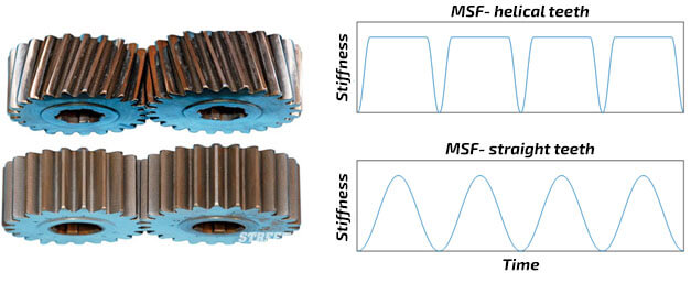
Figure 4. Comparison of meshing for helical teeth and straight teeth and their schematic meshing stiffness function (MSF) [6]
The practical consequence of this phenomenon is that, in addition to operating parameters, the design solutions of individual gears also have a very large impact on the spectral pattern of good and damaged gear. In the literature, the analysis of the first three harmonics of the meshing frequency (GMF) and their first double sidebands is the most common. A typical diagnostic clue is, for example, that an increase in sideband amplitude above GMF (or a GMFx2 amplitude greater than GMFx1) is indicative of significant gear damage. And yes, it often happens, but you can also try to compare the works of Prof. Bartelmus [7], in which the first 15 harmonics of the meshing frequency with modern epicyclic gears for wind turbines, which practically do not generate the GMF frequency, are analyzed. Notes and references to the main aspects of designing such gears can be found in [8]. It is worth noting that these discrepancies result from the fact that different gear designs are characterized by very different work of the teeth (so the meshing stiffness function), which means that when working in the same conditions, their teeth undergo different deformations, generating different modulation values – and thus we arrive at the final different levels of GMF “fringes” and sideband “fringes” on the spectrum. To sum up, the flatter the MSF function (see right side of Figure 4 – top), the better the gear work in general (the deflection of the teeth is smaller), and as a result, the GMF component has a smaller amplitude.
Thirdly, let us note that gears are systems, confined by a housing which is characterized by an extremely complicated joint function of transition from the source of the gear defect to the sensor. Figure 5 shows exemplary paths that the damage signal can follow for various damages to the components of the epicyclic gear in the planetary configuration.

Figure 5. Scheme of the fault signal transition function [3]
In Figure 5, the paths for the meshing component between the planet and the main gear, and the planet and the sun gear are marked. As you can see, in both cases, the same component follows different paths to the place where the vibration sensor is located, as well as from different sides of the housing.
Practical diagnostics
Summing up the information from both posts about gears – we would like to draw the reader’s attention to the observation that there is no such thing as one spectral pattern for a given gear, and it is difficult to imagine one spectral pattern for different types of gears in a proper technical condition. Let us remember that the gear signal spectrum is the result of many factors – not only its technical condition but also design features and operational parameters. Consequently, it is unfortunately quite easy to obtain similar spectra for two different transmissions, one of which is in good working order and the other is not. It is also very easy to obtain significantly different spectra for the same gear in a given technical condition for different parameters of its operation or different locations of the sensor. Moreover, the dependence of the observed spectral components on the operating parameters, i.e. mainly on the rotational speed and load, is usually completely different for different gears, depending on their design and size (i.e. nominal power). As a consequence, the spectral components generated by some transmissions show a more significant dependence on the change in power and others on the change in speed – and this statement is often true only in certain ranges of operating parameters. Okay, but how do you deal with all this? – Let us finish with some practical tips:
✔️ Record vibrations on the housing as close as possible to the bearing nodes
✔️ Record vibrations in the same place and direction at all times
✔️ Compare signals (trends) from the same sensor with the same mount
✔️ Keep a minimum of 40% of the gear nominal load
✔️ Follow the minimum working time to reach the nominal oil temperature (maybe as long as 1 hour)
✔️ Record signals with as little rotational speed change as possible (generally, the higher the rotational speed, the better)
✔️ Check how many GMFs the gear can generate (track at least 3, but sometimes up to a dozen)
✔️ Do a simplified modal analysis (hit the case and see how the amplitude-frequency characteristics will overall affect the tracked spectral components)
✔️ Find out what kind of teeth the gear has to estimate the ease of generating GMF vs. SB
✔️ Make sure that the characteristic frequencies have been calculated correctly
Use the TSA technique, or at least averaged spectra in order analysis (typically using full resolution spectra can change component levels by up to a half!)
Good Luck!
- [1] Dobrzański T., Rysunek Techniczny Maszynowy, Wydawnictwo Naukowe PWN, Warszawa 2020
- [2] https://en.wikipedia.org/wiki/List_of_gear_nomenclature
- [3] C. M. Viduna, PhD Thesis, 2009 (https://theses.eurasip.org/media/theses/documents/molina-vicuna-cristian-contributions-to-the-analysis-of-vibrations-and-acoustic-emissions-for-the-condition-monitoring-of-epicyclic-gearboxes.pdf)
- [4] J. Ferguson, „Short cuts for analyzing planetary gearing” Mach. Des., vol. 55, pp. 55-58, 1983
- [5] Franz Kurth, Efficiency Determination and Synthesis of Complex-Compound Planetary Gear Transmissions, Technischen Universität München, 2012
- [6] Michael Fernie, The Advantages And Disadvantages Of Straight Cut Gears, 2016 (https://www.carthrottle.com/post/the-advantages-and-disadvantages-of-straight-cut-gears/)
- [7] Bartelmus, R. Zimroz, A new feature for monitoring the condition of gearboxes in non-stationary operating conditions, MSSP, 2009 https://www.sciencedirect.com/science/article/abs/pii/S0888327009000132
- [8] C. Halse, Wind Turbine Drivetrain Development, 2012 https://www.nrel.gov/wind/assets/pdfs/05_1_halse_wind_turbine_drivetrain_development.pdf