A(M)Cademy of VIBROdiagnostics
#4 What is imbalance?
Imbalance is one of the most frequent damage states in the most numerous type of rotor machines, i.e. working at the average range of rotational speed (120 RPM – 3000 RPM). In the engineering jargon, the imbalance is often called as “unbalance”, or maybe the most often “misalignment”.
Where does it come from?
There are multiple sources of imbalance. Besides errors occurring during assembly, imbalance in some machines is the result of their natural degeneration, e.g. decay of rolling bearings. In others, like fans, may be a consequence of erosion or contamination embedded in the blades. Finally, imbalance might be caused by static deformations of the shafts, e.g. thermal deformation. In all cases – as the name suggests – imbalance comes from uneven (so “unequal” or “imbalanced”) distribution of forces acting on a shaft. The general cause is that the centre of mass and the centre of rotation are not aligned.
From the scientific point of view, dynamic analysis of shafts’ work (known as “Rotordynamics”) is an enormously important issue and has been intensively analyzed for well over 100 years (W.Rankine -1869, G. de Laval – 1889, H.Jeffcot -1919) and is full of relatively difficult terms ( e.g. modal matrixes, eigenvalues of a system, differential equations), however for our purposes we can deal without them, because we will focus on the most popular, quite small machines with rolling bearings, which work (especially during start-up) does not require close attention.
To sum up, the imbalance can be the result or the reason for other damage, or both at the same time. What is important, is that a relatively large imbalance acts in a destructive way on every element of a machine, because it creates additional forces acting on other elements (e.g. toothed gear and bearings) which in general are not designed to balance them.
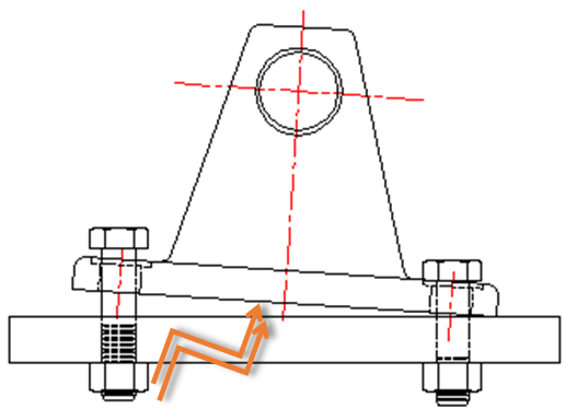
Picture 1. Damage to the foundation of a rotor machine as a result of imbalance
As a consequence, imbalance reduces the fatigue strength of working elements and can result in foundation cracks (Picture 1), as well as often increasing the level of noise emitted by the machine.
Detection
Imbalance is connected to the “unequal” work of a shaft and in the most typical scenario generates the so-called “component 1x1”, which is a sinusoidal component with the frequency in [Hz] that is equivalent to the rotational speed of the shaft [RPM] divided by 60, and the amplitude that depends on the magnitude of the generated centrifugal force and spectrum type. While analyzing the imbalance component it is important to note that the value of centrifugal force increases more rapidly than rotational speed:
F= ω^2*r
Where:
F – the value of the centrifugal force
ω – rotational speed (angular)
r – radius of (mass) imbalance (distance from the centre of mass to the rotation axis)
On the frequency spectrum, the imbalance component resides in the place corresponding to the rotational speed of the machine in [Hz], whereas on the order spectrum, the place corresponding to the gear ratio in regard to the shaft on which the rotational speed is measured (so in machines with only one shaft the value will always be “1”) which is shown in Picture 2 for an exemplary, only shaft of a rotor machine which rotates with the speed of 3000 RPM (50 Hz).
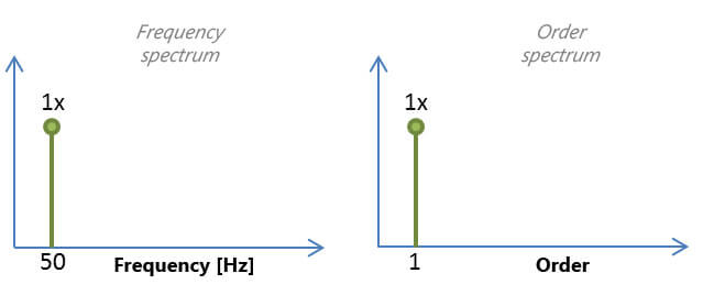
Picture 2. Component 1x in the frequency and order domain respectively.
Therefore one can assume that from the point of configuration and identification on the spectrum, the imbalance component Shaft 1x is usually the simplest spectral component to analyze. The true diagnostic challenge comes from the fact that said component is also generated by a great deal of other damage and in the case of certain machines (e.g. piston machines) is present virtually all the time, regardless of the technical state.
Laboratory example
Picture 3 depicts the AV TEST BENCH stand, which enables us to introduce a controlled state of imbalance thanks to screws mounted to discs on the Slow Shaft (SS). As a matter of introducing an additional force, screws M8 were mounted on the disc, and then the rotational speed (of the fast drive shaft) was monotonously increased within the range of 1000 RPM – 3000 RPM. Due to the gear ratio (23/67), the speed of the slow shaft, affected by the imbalance, was between (1000 RPM*26/67) =343 RPM and (3000RPM*23/67)=1030 RPM.
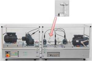
Picture 3. Introduction of imbalance at the AV TEST BENCH stand
In this case, imbalance concerns the Motor_bearing_SS component generated by the Slow Shaft with a ratio of 23/67 in regard to the drive shaft. Picture 4 shows an exemplary frequency spectrum with a marked Slow Shaft 1x component. Based on the configuration of the monitoring system and machine diagnostics, the peak amplitude within the range of 10-25Hz is calculated, which is depicted in Picture 4.
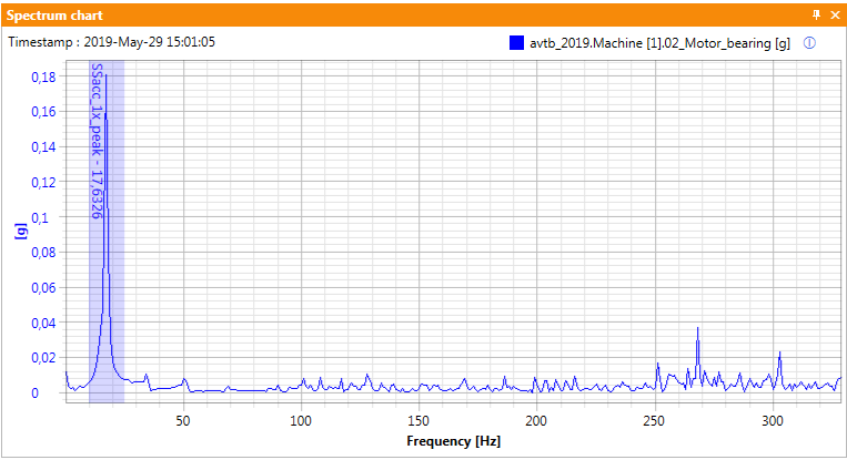
Picture 4. The frequency range of the Slow Shaft x1 component.
What is crucial is that in the case of applied “Peak” analysis, the width of the frequency band can be slightly modulated without influencing the result of the analysis, which is not true with Power and RMS analysis, which normalize the result with regard to the width of the applied band. Picture 5 shows the rotational speed and the growth of the forces related to imbalance during the controlled start-up of the machine and selected trends.

Picture 5. Imbalance test – trends.
The red series represents rotational speed RPM, which increased from 1000 RPM to 3000 RPM within a few minutes. The green series represents the value of the effective speed of vibrations VRMS in the band of 10 Hz to 1000 Hz. It is easy to notice that the imbalance component Slow Shaft 1x (with values ranging from 100*23/67/60 = 5.7 Hz to 3000*23/67/60 = 17.2 Hz) appears in the band of the VRMS estimator only when the speed is higher or equal to:
Fast Shaft speed > 10Hz*67/23*60 RMP/Hz
Fast Shaft speed >1748,
Which in our case comes down to
Fast Shaft speed ≥ 1800 RPM,
so after around the 48th minute in Picture 5. According to Picture 5, the VRMS estimate generally enables good detection of improper technical state of a rotor machine caused by imbalance, however, only the narrowband estimate Slow Shaft 1x (blue series), which definition is shown in Picture 4, allows us to identify the reason behind the increase in VRMS value – which is the state of imbalance.
Modification of 1x component by the critical speed
Although it s a simple rotor machine that is described here, it is worth remembering that even for those machines dynamic phenomena related to so-called critical speeds might occur, which could have a crucial effect on the level of 1x component, similarly to other components coupled with the phase (i.e. rotations of the shaft), as shown in Picture 6.
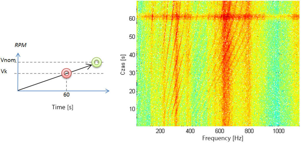
Picture 6 a) The idea of critical speed, b) Passing through critical speed (spectrogram).
Picture 6a illustrates the critical speed Vk, through which the machine passes before achieving the nominal speed of the shaft Vnom. Picture 6b shows an exemplary real-time signal from the start-up of a rotor machine, which goes through the critical speed after the 60th second of measurement.
Use of measuring equipment
AMC VIBRO company offers detection, identification and the overview of the level of imbalance component as the component defined by the user, as well as characteristic component automatically calculated by the system based on the kinetostatic model.
Table 1. The juxtaposition of the AVM family devices based on characteristic frequencies
|
|
| |
| Detection of imbalance using VRMS analysis | ✔️ | ✔️ | ✔️ |
| Detection and identification using Shaft 1x analysis in the frequency domain, configured by the user | ✔️ | ✔️ | |
| Detection and identification using Shaft 1x analysis in order domain, configured by the user | ✔️ | ||
| Detection and identification using Shaft 1x analysis in the frequency domain, automatically configured | ✔️ | ||
| Detection and identification using Shaft 1x analysis in order domain, automatically configured | ✔️ |
1Complex explanation of the term can be found in the post No. 3 – “Characteristic frequencies”


