products for monitoring and diagnostics of machinery
A(M)Cademy of VIBROdiagnostics
#12 Wireless sensors – pitfall or a new trend?
Many companies are now offering wireless vibration sensors. You can find them within any price range, from very expensive to cheap sensors, and naturally with different parameters. This variety raises questions among monitoring and diagnostic systems users asking about the value of these products. What are the advantages and disadvantages compared to “traditional” systems that have been present in the market for many years? We will address this topic thoroughly in this article.
Similar to traditional accelerometers, wireless vibration sensors typically measure acceleration using the properties of piezoelectric elements. In short, they employ the same conversion of physical signals, i.e.:
force -> current -> voltage -> acceleration signal
Some sensors utilize accelerometers in MEMS technology, but the fundamental characteristics of both variants are quite similar. From a user perspective, the use of wireless sensors differs significantly from using traditional devices. The situation can be compared to a passenger on an aeroplane embarking on a long journey but realizing at the airport that due to imposed restrictions, they can only carry a small carry-on bag. Such a bag cannot accommodate all the items that seem essential, but let’s consider whether it’s better to have it with us or not have it at all. The essence of wireless sensors is similar. One must realize both their limited functionality and their irreplaceable advantages to properly position them in the architecture of a continuous monitoring system. An example application of wireless sensors is presented in Figure 1.

Figure 1. Diagram of a system utilizing wireless sensors
As shown in Figure 1, wireless sensors are typically placed on auxiliary machines that are not easily accessible with wired sensors under normal conditions. Since minimizing energy consumption is one of the priorities of wireless vibration sensors, data from these sensors is usually not directly transmitted to the central computer. Instead, they pass through an intermediate unit located nearby, indicated as the “Gateway” in Figure 1. The desired feature of wireless sensors, as indicated in Figure 1, is the ability to integrate them with wired sensors within a single Condition Monitoring System (CMS). Wireless sensors take measurements much less frequently, so they are often installed in locations where measurements were previously performed using portable equipment.
Radio Communication Range
Wireless sensors utilize radio frequencies to transmit information. Therefore, it is essential to assess the radio wave propagation conditions in a given environment. The operating frequency band of the sensor is of great importance. As a general rule, higher radio frequencies provide greater bandwidth but shorter communication range. For the popular 868 MHz band (equivalent to the 915 MHz band in the United States), achievable ranges of approximately 1 kilometre or more can be achieved in an open space. However, the range sharply decreases in a machinery room where there are walls and numerous metallic elements. Furthermore, if the machine is enclosed in a metal casing, the sensor cannot operate inside as the casing acts as a Faraday cage and cuts off communication.
Power Supply for Wireless Sensors
Wireless vibration sensors are designed for measurements in hard-to-reach locations, and therefore, a key requirement is for them to operate on a single battery for several years. This is the main difference between such sensors and other everyday wireless electrical devices we use (such as speakers, phones, etc.). Consequently, wireless vibration sensors are designed to work for several months without the need for battery replacement. As a result, the signal registration logic, parameters of recorded vibration signals, and signal processing methods are significantly limited compared to wired systems powered by the grid. This is illustrated schematically in Figure 2, comparing the sensor placement capabilities between the two types.
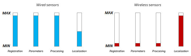
Figure 2. Comparison of selected aspects of wired and wireless sensors
Below, the details of the mentioned limitations are discussed:
Registration Logic
Unlike continuous monitoring systems, wireless sensors wake up periodically, collect data, process it, and then go back to sleep. Typically, the wake-up process occurs synchronously, for example, once every 8 hours. In advanced systems (e.g., AVS 2000R), it is possible to increase the registration frequency as the vibration levels increase, as shown in Figure 3.
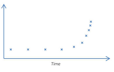
Figure 3. Registration frequency dependency on vibration levels
The dynamic registration presented in Figure 3, on the one hand, reduces battery consumption when “nothing is happening” and focuses on more accurate measurements when damage is developing.
Vibration Signal Parameters
The most significant parameters for acquiring vibration signals are the signal length and sampling frequency. In typical CMS systems, recorded signals have lengths ranging from 1s to 10s. As a general rule, the slower the machine rotates, the longer the recorded signal should be. If the monitoring is focused on detecting unbalance, misalignment, or overall vibration levels according to ISO 20816, a sampling frequency of 2 kHz may be sufficient. On the other hand, if the system is intended for early detection of faults in rolling bearings or other phenomena that generate structural vibrations, a sampling frequency of around 20 kHz or higher is required. As a result, for the given ranges of signal length and sampling frequency, the number of samples in the buffer ranges from 2,000 (1 s * 2,000 samples/s) to 200,000 (10 s * 20,000 samples/s).
For currently available wireless sensors, the upper limit of the number of samples is practically unachievable, mainly due to processor power and memory size limitations. Due to available computational libraries (e.g., FFT), wireless sensors often utilize buffers with a length of 2^n samples for further calculations. With this value, a sensor can collect, for example, a 1-second signal with a sampling frequency of fs = 2,048 Hz (2,048 samples) or a signal with a length L = 0.125 s and a sampling frequency of fs = 16,384 Hz (also 2,048 samples). In the first case, the spectral resolution is 1 Hz, while in the second case, it is as high as 8 Hz. The following equations are used in calculations:
Number_of_Samples = L * fs
Resolution = 1 / L = fs / Number_of_Samples
A graphical illustration of these relationships is shown in Figure 4. It is important to note that vibrations measured by accelerometers (i.e., absolute vibrations) are subject to significant random component variations (i.e., they are noisy). Therefore, it is generally recommended to perform multiple averaging of recorded cycles. In practice, this means that it is beneficial for the processed vibration signal to contain several periods of the analyzed components. For example, 1-second signals are suitable for analyzing shafts rotating at a minimum speed of 600 RPM (i.e., at least 10 Hz).
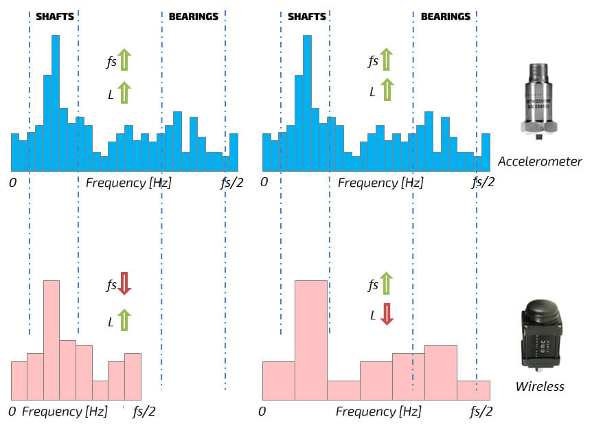
Figure 4 Acquisition parameters and their impact on resolution and spectral range
As shown in Figure 4, the settings for signal registration parameters in wireless sensors involve a choice between a wider frequency range (enabling detection of a larger set of faults) and better spectral resolution (allowing more precise identification of faults generating low-frequency components, mainly in drive shafts).
Signal Processing Methods
Due to their characteristics, wireless sensors do not measure signal phase (i.e., the instantaneous rotational speed of the machine) and, therefore, do not perform order analysis. From a practical standpoint, this means that they are designed for continuous monitoring of machines operating under steady operational conditions. Along with the limited purpose of wireless sensors and their restricted signal acquisition capabilities, there are limitations in the signal processing methods that can be implemented in such sensors. Typical wireless sensors measure the following values:
- PP Acceleration: the peak-to-peak value of the vibration acceleration signal
- RMS Acceleration: root mean square value of the vibration acceleration signal
- RMS Velocity: root mean square value of the vibration velocity signal (including ISO 20816)
- PP Envelope: the peak-to-peak value of the vibration acceleration envelope signal
- RMS Envelope: root mean square value of the vibration acceleration envelope signal
The list of diagnostic indicators calculated for wireless sensors is much more limited than for wired sensors and typically focuses on classical broadband values. More advanced systems, such as modules from the AVS 2000R series, additionally allow for narrowband analyses, enabling the identification of specific machine component faults. Some systems also record the temperature at the measurement location, which is a valuable feature.
The computational methods for analyzing velocity signals (VRMS) and envelope signals (EnvPP, EnvRMS) are similar to those used in wired systems. However, due to limited flexibility in the length of processed signal buffers, the configuration parameters for these analyses are relatively limited and mainly involve selecting the cutoff frequencies of the high-pass and low-pass filters from a restricted list. The RMS value of the velocity signal (VRMS) is typically measured in the range of 10 Hz to 1,000 Hz, following ISO 20816, and due to the limited length of the analyzed signals, it does not cover machines with rotational speeds below 600 RPM.
Summary
First and foremost, it is important to remember that wireless sensors have their specific place in the diagnostics of technical machinery. They should not be used as substitutes for wired systems – their purpose is where cable installation is practically impossible or very costly. When configuring wireless sensors, one should resist the temptation to set “exaggerated” acquisition and signal processing parameters, as it will impact battery life. Compared to wired sensors, wireless sensors may offer limited capabilities, but with proper placement, they can provide significant benefits for maintenance services. The number of configuration nodes is limited, but the absence of complex signal-processing configuration methods often proves advantageous for many operators. They are best suited to replace measurements performed with portable vibration meters, especially in hard-to-reach areas. Such measurements are typically conducted every few days, weeks, or even months. Conducting measurements multiple times a day provides users with much more valuable information.
Wireless system AVS 2000R + AVM GATEWAY
| Modules from the AVS 2000R series are wireless, dual-channel, configurable devices that enable continuous monitoring and diagnostics of machines. The module allows for transmitting information about the machine’s condition using a radio network. Measurement data is collected cyclically according to the configured interval, and in case of communication issues, it is stored in the device’s internal memory and transmitted when the connection is established to ensure measurement continuity. The sensor itself determines the vibration signal parameters, which results in much less data being transmitted. A modern feature of the module is the ability to track the vibrations of selected machine components. |  |
| The main functions of the AVM GATEWAY are network management of sensors and collecting and processing data from devices. The gateway acts as a client for the OPC server and is compatible with the Modbus TCP communication protocol. This allows for quick and easy integration of AVS2000R sensors with control systems (or SCADA). The module also includes a built-in web server, which enables system configuration by the user and browsing of collected data. All that is needed is a standard web browser. |  |