products for monitoring and diagnostics of machinery
A(M)Cademy of VIBROdiagnostics
#1 Acceleration, velocity and displacement of vibrations
Vibrations are a periodic displacement of a mechanical object over time. Along with an increase of temperature and friction, they are a form of dissipation of energy provided to an object such as a car, plane, fan, pump or washing machine. Because of that, vibrations can tell us a lot about the technical condition of a device.
In measuring systems, vibrations can be defined as one of three different physical quantities: a signal displacement, velocity or acceleration. Displacement is mainly used in monitoring the technical condition with regard to large shafts mounted on plain bearings (one can use them to make e.g. so-called orbit plots for turbo sets). The velocity of vibrations is the primary measure according to vibrations norms (such as ISO 20816) because it most accurately reflects dangerous forces acting on a machine in the widest frequency range. Choosing the right measurement quantity is crucial, it influences the quality of the measurement and – obviously – the price. Vibrations acceleration is nowadays the most frequently used method of measuring vibrations, since acceleration sensors are the least expensive and the easiest to use, they allow us to analyze structural vibrations and compute their velocity and displacement. So how do these 3 quantities relate to one another?
A little theory
Picture 1 shows an exemplary, sinusoidal signal of acceleration (Acc) with the frequency of 100 Hz and the amplitude of 7 [g], converted respectively into a signal of velocity (Vel) and displacement (Dis). Notice how the units of the signals change from [g] to respectively [mm/s] and [mm]. In the example below, the amplitude of the velocity signal equals 109.3 [mm/s], because calculating the amplitude of the velocity signal requires both unit conversion (1 [g] = 9.81 [m/s2] = 9810 [mm/s2]) and rescaling of the amplitude by the value: 1/1/(2∙π∙f), in our case f = 100[Hz]. The amplitude of the displacement signal is calculated by once again multiplying the value of the velocity signal amplitude by the rate 1/1/(2∙π∙100). As shown in Picture 1, the conversion of physical units does not change the frequency value of the components. Using this method one can convert between quantities describing vibrations. It is worth adding, that, in general, the acceleration signal is the noisiest, and the displacement signal the least.

Picture 1. Acceleration, Velocity and displacement of a sinusoidal component
In case of spectrum analysis, the choice of physical value translates to a change of the spectrum shape. As shown in Picture 2, the acceleration signal enhances components with high frequency, and the displacement signal boosts components with low frequency.
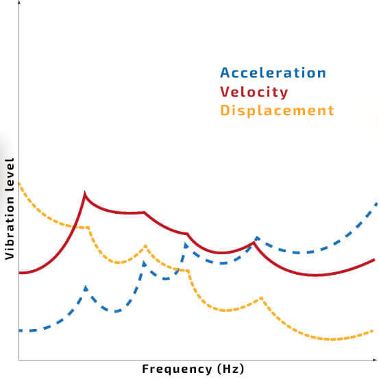
Picture 2. A comparative scheme of acceleration, velocity and displacement signal spectrum
Practical Analysis
What does it matter in practice? Values of the vibrations amplitudes will change depending on the chosen physical quantity. If the velocity of the signal is constant, with increasing frequency, the value of the acceleration increases, and the value of the displacement decreases. Similarly, with decreasing frequency, the value of the displacement rises, while the value of the acceleration decreases, as shown schematically in Picture 3. It depicts the change of vibrations physical quantities for the vibrations signal with a frequency of 5 Hz and 500 Hz.

Picture 3. Schematic changes of component values
Analysis of different physical quantities is convenient, while simultaneously monitoring a number of components generated in a broad frequency band. Picture 4 depicts a rotating machine consisting (from the left) of a propulsion motor, parallel gear, shafts, bearing assembly and braking motor. The picture schematically shows a general type of components generated by the propeller shaft, gear and bearing, in addition, one marked a typical range of frequency, within which malfunctions of those elements might occur. Since propeller shafts of average machines do not exceed revolutions of 50-60 Hz, the velocity of their vibrations or displacement (especially for plain bearings) is frequently monitored. In the case of toothed gear, up to around 160 Hz (involves all crucial harmonics), a measurement of the velocity of vibrations is recommended, and over 500 Hz a measurement of acceleration is typically used. In case of exciting structural vibrations, typical for damaging plain bearings and certain damages of toothed gears, a measurement of acceleration is required, for rotating machines, in general, exhibit structural vibrations ranging from 2kHz to 20 kHz.
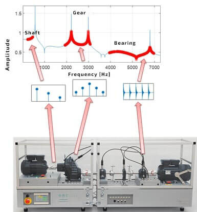
Picture 4. Frequency bands exciting by the elements of a rotating machine.
Application of measurement equipment
AMC VIBRO company offers diagnostics of industrial machines, using modern AVM 1000, AVM 2000 and AVM 4000 series devices. AVM1000 series are 1-channel easy-to-use systems allowing the reading of the peak value 0-PEAK and the root mean square of vibrations, RMS of an acceleration signal or a velocity signal. AVM2000 series offers the same functionality as the AVM 1000 series, additionally, the device enables us to analyze the envelope signal of an acceleration signal, as well as determine the power in designated frequency bands both for a velocity and acceleration signal. AVM4000 system makes it possible to measure any physical quantity in EPE (ICP) standard and determine the user’s analysis from any chosen quantity of a signal, i.e. acceleration of vibrations, their velocity as well as their displacement. The main characteristics of a device in terms of processed physical quantities are shown in Table 1. All of those quantities are computed inside modules from the signal of the acceleration of vibrations.
Table 1 Comparison of devices from AVM family in terms of processed physical quantities
| AVM 1000 | AVM 2000 | AVM 4000 | |
| 0-Peak of acceleration | ✔️ | ✔️ | ✔️ |
| 0-Peak of velocity | ✔️ | ✔️ | ✔️ |
| RMS of acceleration | ✔️ | ✔️ | ✔️ |
| RMS of velocity | ✔️ | ✔️ | ✔️ |
| Acceleration envelope | ✔️ | ✔️ | |
| Power in acceleration bands | ✔️ | ✔️ | |
| Broadband user’s estimates of the acceleration signal | ✔️ | ||
| Broadband user’s estimates of the velocity signal | ✔️ | ||
| Broadband user’s estimates of the displacement signal | ✔️ | ||
| Narrowband user’s estimates of the acceleration signal | ✔️ | ||
| Narrowband user’s estimates of the velocity signal | ✔️ | ||
| Narrowband user’s estimates of the displacement signal | ✔️ |
Book recommendation